
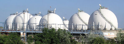
Wood storage is generally considered a prerequisite for a fireplace. It is much more convenient to prepare a large wood pile than continually gathering wood to feed a fire. Such fuel storage goes back to the beginnings of human civilization. Today, however, fuel storage looks quite a bit different and is more complex than a woodpile in the backyard. To the right is a picture of one of the simplest energy storage technologies today, the fuel tank. It can be filled with energy at one point in time and depleted at another, like for all energy storage systems. The kind of stored energy can be electric energy in a capacitor or, as we see here, chemical energy in a fuel tank. Similar to rechargeable batteries, filling and emptying of a hydro storage system is done using electric energy. But the stored energy is potential energy for hydro electric power and chemical energy for rechargeable batteries.
Energy loss is a crucial problem for all energy storage approaches, except fuel. The charging/discharging process warms a battery. This heat energy is an energy loss for the battery. Similarly, pumped-storage hydroelectric power stations convert about one quarter of their electrical input into unwanted heat energy.
As we look beyond fuels based on finite resources, there is a growing focus on energy storage, due to the needs of wind and solar methods of producing energy. The time discrepancy between generation and consumption of electric energy requires storage systems.
This page describes how fuel systems work, how fast their energy output is, how their efficiency is related to energy input and energy output, and what the costs for building and operation of the facilities are. Larger presentations can be found in thes review of Ausfelder et al. or at Wikipedia which has a list of energy storage projects. We divide the page into 1. Hydroelectric pumped storage, 2. Compressed air storage, 3. Flywheel storage, 4. Heat storage, 5. Capacitors and coils, 6. Batteries and 7. Power to gas storage.
Most hydroelectric power comes from conventional dams with reservoirs which can provide peak generation at times of peak demand. The turbines have a start-up time of a few minutes. Countries with a high amount of conventional hydroelectricity like Norway or Canada don't need large capacities for additional energy storage.
Pumped-storage hydroelectricity uses, at times of low demand, electrical generation capacity to pump water from the lower into the higher reservoir. In about 1930, reversible hydroelectric turbines were introduced, which operate as both turbine-generators and in reverse as electric motor driven pumps. The first large-scale use of pumped storage was begun in Niederwartha near Dresden, Germany, with a fall height of 150 m and six 20-MW pumps/generators, and near New Milford, Connecticut in the US, where the Connecticut Electric and Power Company used two 6-MW pumps and one 33-MW generator to pump water from the Housatonic River to a storage reservoir 70 m above.
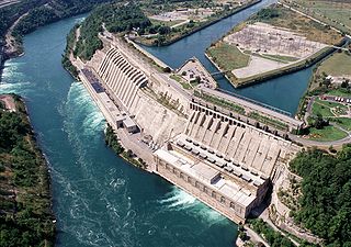
In 1922, the Sir Adam Beck Generating Complex at Niagara Falls, Canada, was in 1922 the first large-scale hydroelectric generation project in the world, see figure below at left. Now it includes an additional large pumped storage hydroelectricity reservoir to provide an extra 174 MW of electricity during periods of peak demand.
The second largest hydroelectric pumped-storage power station today is the Bath County Pumped Storage Station in Virginia, USA, with falls that are almost 400 m high and a power of 3 GW. The average efficiency of pumped-storage power stations is 75−80%. Additional losses occur in the power lines to and from the stations.
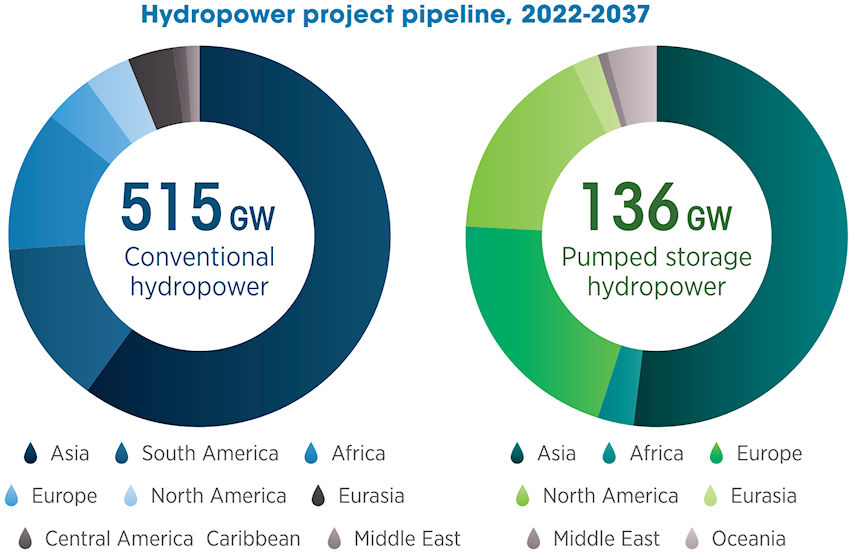
The energy production by conventional hydroelectric power (from dams with reservoirs) was in 2022, according to the 2023 Renewable Energy Statistics of IRENA , 4 401 TWh worldwide, 1 339 TWh in China, 376 TWh in EU, 363 TWh in Brazil, 217 TWh in Russia, 144 TWh in Norway, and 274 TWh in U.S. Pumped hydrostorage power was worldwide 137 GW, China 46 GW, Europe 29 GW, Japan 22 GW, and U.S. 19 GW. Hydropower visions of the US Department of Energy describe, how storage power in the U.S. could be doubled by 2050 with low cost financing. The ecpected worldwide progress between 2022 and 2037, see figure below at right, was taken from the IRENA report The Changing Role of Hydro Power.
Compressed air energy storage has long been used in small scale applications, such as fireless locomotives. Two diabatic compressed-air demonstration projects are in use now. The project in Huntorf, Germany, has been in operation since 1978. It has a power of 321 MW for a storage time of 2 h and an electrical efficiency of 42%. The relatively low efficiency is caused by the adiabatic process. Compression produces heat during charging, and later decompression causes cooling during discharging.
In contrast to diabatic systems, adiabatic procedures use thermal storage in addition to the compressed-air reservoir. It makes the heat of compression available for decompression. The theoretical efficiency of adiabatic storage should be 100% with perfect insulation. But in practice, round trip efficiency is expected to be 70%, see Wikipedia. At present, there are no large scale adiabatic compressed-air energy storage plants.
All power stations consisting of turbines and generators have a huge flywheel mass which stores kinetic rotational energy. After switching off the driving force, electricity generation persists only for a few minutes. Two common problems of flywheel energy storage are thus: Investment is expensive and the time period for power delivery is limited. Flywheel energy storage systems consist of a flywheel supported by rolling-element bearing connected to a motor-generator. Early flywheel systems used large steel flywheels, rotating on mechanical bearings. More advanced systems with carbon-fiber composite rotors now benefit from a higher tensile strength than steel, and the use of magnetic bearings instead of mechanical bearings reduces friction.
A flywheel 20-MW facility including 200 flywheels has been in operation in Stephentown, NY, since 2011. It was built and is managed by Beacon Power, provides frequency regulation to the electricity grid, and performs between 3,000 and 5,000 full depth-of-discharge cycles a year. Single Beacon Powers 400 modules are configurable from 160 kW for 5 minutes to 50 kW for 35 minutes, it produces 30 kWh usable energy at full charge, with a response time of about 20 ms from receipt of signal to start of changing output and round trip efficiency of 85%.
Domestic storage heaters use cheaper nighttime electricity to heat a water container or ceramic bricks, which in turn release this heat during the day. It is economically justifiable, if an old two-tariff or a new smart electricity meter records the electricity parameter together with the present price, which is very different during the day (expensive) and during the night (less expensive). The electric storage heater came into use in the middle of the 20th century, and a new generation of these heaters are now offered (see storageheatersdirect for example). Other recent and growing applications of domestic heat storage are heat exchangers on roofs and heat storage in houses to help heat hot water, if the sun shines. Another recent and growing application of the domestic heat storage is that a heat exchanger on the roof and heat storage in a house help with hot water, if the sun shines.
There is a difference between "thermal storage" or "sensible thermal storage" and "latent heat storage", see Wikipedia. The former means a temperature change of the material without a phase transition. For the former, water is commonly used between ambient temperature and 100 °C. For the different high-temperature steam accumulator see Wikipedia. Water has a specific heat capacity of about 4.2 kJ kg−1 K−1. Thermal oil can be used between ambient temperature and the boiling temperature of about 350 °C with a specific heat capacity of about 2.1 kJ kg−1 K−1. Natural stones, ceramics or concret can be used up to 100 °C ore more, but have a lower specific heat capacity of about 0.9 kJ kg−1 K−1.
Large-scale solar power stations use molten salts, e. g. a mixture of sodium nitrate, potassium nitrate and calcium nitrate with a specific heat capacity of about 1.3 kJ kg−1 K−1. The salt melts at about 130 °C and is kept as a liquid in a "cold" storage tank up to about 300 °C. The liquid salt is pumped through panels in a solar collector where the focused sun heats it to about 560 °C. Finally it comes to the hot storage tank, where it can be stored for up to a week.
Large-scale "latent heat storage" tanks with a divider plate to hold both cold and hot molten salt, are under development for next generation storage by means of molten salts. Heat storage per unit volume is expected to double in comparison with the older molten-salt storage technology. In Carboneras, Spain, in 2010–2011 a pilot facility of the DLR was working for about 3000 h and 95 cycles with a capacity of 700 kWh. The filling was 14 t sodium nitrate with a phase transition at 305 °C.
Energy storage in capacitors is used the most by cyclists. A supercapacitor prevents the quenching of light during a short stop. Energy storage in capacitors is described on the page Field energy. The disadvantages of supercapacitors for energy storage are their low voltage (2−3 V), self-discharge (loss of half energy) within a month, and high investment costs of $10,000−20,000 per kWh. Advantages with respect to batteries are the high load and unload carrying capacity during charge and discharge and the high number (105−106) lifetime cycles. Energy storage in coils is even more expensive. Their economic use will requires the technical availability of room-temperature superconductivity.
Different types of batteries are described on the page Batteries. A large lithium ion battery power station is the Hornsdale Power Reserve adjacent to the Hornsdale wind farm in the north of Adelaide, Australia. Since 2018, the plant has provided a total of 129 MWh of storage capable of discharge at 100 MW into the power grid. A large sodium sulfur battery system of NGK Insulators has been in Abu Dhabi since 2019, the capital of the United Arab Emirates. 15 systems (12 x 4 MW systems and three 20 MW systems) are located across 10 stations with each system able to store energy for six hours. The addition gives 108 MW / 648 MWh in total. All systems can be controlled as a single plant, but also individually when local support to the grid is needed. A list of battery storage power stations refers to lithium ion battery power plants, which are currently in use or planned.
Lifetimes of more than ten years and cycle numbers above one thousand are realized now for batteries. But the energy density is still lower than 150 Wh/kg. Values above 300 Wh/kg are expected within the next ten years, see Batteries.
Power-to-gas (Power-to-fuel) is a technology that converts electrical power to fuel. Presently, the round-trip efficiency is well below 50%. Electrical power converts water into oxygen and hydrogen gas or water plus carbon dioxide into liquid fuel. Both can be stored without loss. It can be used for fuel cells in cars. The use in power stations results in a full energy storage cycle. The latter is not economically viable now, since petroleum gas is much cheaper than electrolytically produced gas. But the research is under progress for a future utilization of the power-to-gas conversion, see Ausfelder et al.
Water is separated by application of electric power into hydrogen and oxygen gas. The electrolysis process can be performed by a proton-exchange membrane electrolysis of water.
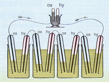
A colored reproduction of the gas cell, originally presented on page Fuel cells, demonstrates on left the acid electrolysis. The flasks of the figure are filled with dilute sulfuric acid. The tubes covering the platinum electrodes are filled with oxygen or hydrogen before use. A current is produced, which can be used to convert the water in the upper black vessel into oxygen and hydrogen.
Technologies of water electrolysis were described by Burton et al. Alkaline electrolysis works in the temperature range 40−90 °C with a liquid basic electrolyte. Charge carrier is OH−. A diaphragm between anode and cathode is penetrable for the charge carriers.
are the cathodic and anodic reactions, respectively. The world's largest station with a power of 156 MW exists since more than fifty years on the Aswan Dam in Egypt and produces 33,000 m³ hydrogen per hour.
Acid PEM-membrane electrolysis works in the temperature range 20−100 °C with a solid electrolyte. The charge carrier is H+ .
are the cathodic and anodic reactions, respectively. PEM-membrane electrolysis is favorably than the basic one for small-scale applications.
High-temperature electrolysis works in the temperature range 700−1000 °C with a solid oxide electrolyte. Charge carrier is O2−.
are the cathodic and anodic reactions, respectively. The three approaches are used for the production of hydroxy, which is used for industrial processes or fuel cells, also in cars.